8,02€
Κριτικές πελατών
- Όλες οι κριτικές (193)
- Εικόνα (26)
- Βίντεο (2)
Ταξινόμηση κατά:
Κριτικές μόνο από τη χώρα σας (Greece)
|
Εμφάνιση πρωτότυπου
Ένα μέρος της κριτικής έχει μεταφραστεί αυτόματα.
-
21/07/2017
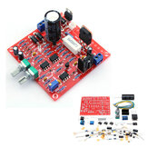
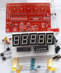
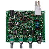
Frequency measurement: I managed to run it only if the input signal is between 4.7 and 5 volts (not to be exceeded). The signal goes directly to pin 3 of the PIC (5V max). An incoming signal amplification circuit must be provided. Quartz measurements: Very poor circuit. It depends a lot on the supply voltage, the temperature and the quartz frequency. Limited use. Measurement examples: (3,2748 MHz -> 0) (4,9152 MHz -> 4,9166) (16 MHz -> 16,001 16,006) (20 MHz -> 20,007) (22 MHz -> 22,007). Strange situation: if the power is about 9 volts, the 4.9152 MHz quartz give these results: -> 14,667 14,669 14,672 14,681 Third harmonica?) Under investigation.
ΣχόλιαΕμφάνιση πρωτότυπου -
06/01/2016
This came with no instructions, but the PCB is labelled with component values so I found it very easy to assemble. A description of how to use the add/subtract functions can be found at http://www.qsl.net/dl4yhf/freq_counter/freq_counter.html (as mentioned by tom_pin in the product discussion). The display is much easier to read if you add a red filter. If I had the chance to make 1 change, I'd provide space on the PCB for 4mm sockets for ground and frequency signal in; then it would be easy to connect different sorts of test lead (e.g. pointy or spring hook).
ΣχόλιαΕμφάνιση πρωτότυπου -
05/05/2015
It says to adjust the xtal frequency to 20.000 MHz. But doesn't say how. I would like to know how. Other than that, mine works excellently.
Σχόλια (1)Εμφάνιση πρωτότυπου -
12/02/2015
I bought two of these and have just put one of them together and it works a treat. I've got a box of crystals, collected over the years from old equipment and so on - In most cases, it displayed a couple kHz off from what the crystal was marked as. You can adjust it to a known exact frequency with the trimmer-capacitor. A friend of mine says he has some 32 kHz clock thingies that is are a damned sight more accurate than the crystals, so we can adjust it with that. crystal marked => read 4.000 MHz => 4.0000 MHz 6.000 MHz => 6.0008 MHz 9.04933 MHz => 9.0496 MHz 14.31818 MHz => 14.323 MHz 52.416 v=> 17.4something MHz * 1/3 of the fundamental It is well laid out, with all the components clearly marked on the PCB. Lack of any documentation is a small negative point, but not a problem, so still 5 stars. There is an extra 22p capacitor which I thought was spare, but in an earlier comment, someone has written a document for it, showing that the extra capacitor can be used if the low frequency readings are unstable. The construction is very straight forward and the other kit I bought will be my nine year old son's first soldering project :) Delivery was also very fast. It was marked as out-of-stock until 05/02/2015, but mine arrived on 10/02/2015.
Σχόλια (1)Εμφάνιση πρωτότυπου -
02/02/2015
Very easy to construct and test. Worked excellent first time after tuning. Good quality components and very high quality PCB. Good stability and good accuracy once setup. If I did have one grumble then it would be the quality of the variable tuning capacitor. Its very sensitive and would benefit from a slightly better quality capacitor to make sure it is accurate all the time, apart from that Excellent. I love it. Well done BangGood, another brilliant product that every toolbox should have, from the Radio Amateur like myself to the novice.
Σχόλια (1)Εμφάνιση πρωτότυπου -
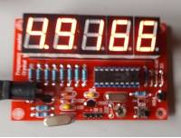
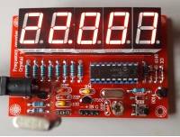
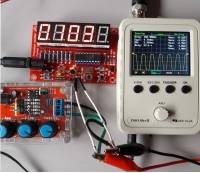
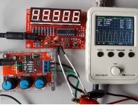
 RudyOVIP2BE19/05/2019
High Quality DIY Frequency Counter and Crystal checker. Works perfect !! Testing a 8700.000Hz crystal and a 50Hz input signal. See Pictures. Recommended !!!!
ΣχόλιαΕμφάνιση πρωτότυπου -
 yuideterVIP1IT04/09/2017
Perfect to read frequency.. For the the price I pay I am very satisfied...
ΣχόλιαΕμφάνιση πρωτότυπου -
06/08/2019
Quite simple to build, useful but not always precise in the measure of quartz
ΣχόλιαΕμφάνιση πρωτότυπου -
RICVIP1BR08/11/2018
Thank YOU Please I did pay in September the RK560 frequency counter meter . Take pictures Photos the Bill Ticket that It did pay in date September 2018. I will wait the RK560 Frequency Counter Meter . Please read see pictures Photos the Bill Ticket. Thank YOU BANGGOOD very very much BANGGOOD.
ΣχόλιαΕμφάνιση πρωτότυπου -
 gabygaVIP2FR12/05/2018
Bon KIT
ΣχόλιαΕμφάνιση πρωτότυπου


Show:
Ίσως σας ενδιαφέρει
-
 16,69€
 -
21,21€
-
11,06€
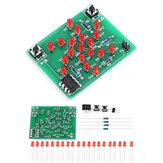
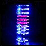
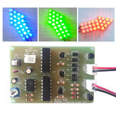
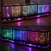
DIY Όνειρο Κρυστάλλινο Ηλεκτρονικό Κύβος Φως LED με Μουσική Φωνή Φάσμα Σετ
-
11,06€
Το σετ παραγωγής του ελεγκτή τρανζίστορ WangDaTao YD-CS με κέλυφος
-
11,98€
-
13,84€
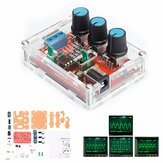
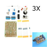
Σετ 3Pcs DC12 DIY ICL8038 Κιτ γεννήτριας σημάτων Συνάρτησης SIN TRIANGLE SQUARE WAVE
-
19,23€
Κιτ ελευθέρας λήψης αεροπορικής ζώνης DIY υψηλής ευαισθησίας - Κλασική έκδοση
-
8,52€
-
17,52€
-
6,45€
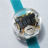
Σετ χρονομέτρου EQKIT® 60 δευτερολέπτων για ασκήσεις συγκόλλησης
-
23,33€
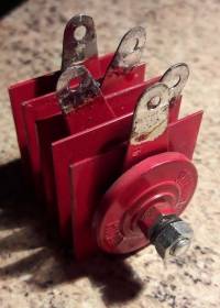
Σετ ηλεκτρονικών ανταλλακτικών DIY για αντιστάθμιση μαγνητικής αιώρησης και μάθηση συγκόλλησης
-
6,36€
-
19,36€
-
6,45€
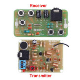
Σετ παραγωγής ηλεκτρονικών walkie-talkie DIY εκπαιδευτικά πακέτα έναρξης συγκόλλησης πειράματος
-
17,52€
-
10,74€
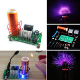
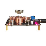
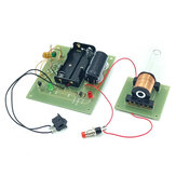
Κιτ Ηλεκτρομαγνητικού Πυροβόλου DIY, Εξοπλισμός Ηλεκτρομαγνητικού Πειράματος
-
45,61€
-
14,75€
-
34,13€
-
8,52€
-
3,68€
-
35,05€
-
18,12€
-
6,88€
Σετ αναπτήρα ΤΕΚΙΤ® με Τόξο DC3-5V 3A DIY Υψηλής Πίεσης Ηλεκτρονικό Αναπτήρα Κιτ
-
11,98€
Πίνακας προενισχυτή σωλήνα 6J1 Valve με χαμηλές συχνότητες σε σετ DIY Musical Fidelity με θήκη
-
15,97€
-
11,98€
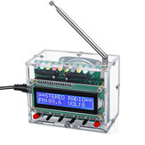
Σετ ηλεκτρονικών εξαρτημάτων / kit Geekcreit® DIY Ραδιόφωνο 51 μονοκύκλων μηχανημάτων ήχου FM
-
6,99€
-
11,71€
-
6,45€
4X4X4 Μπλε Πηγαίο Κιτ LED Cube 3D LED DIY για Arduino Smart Electronics Led Cube Kit
-
10,60€
-
10,60€
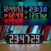
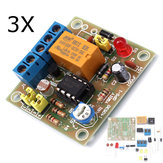
Σετ DIY 5V Πλακέτας Χρονομέτρου Δύο Μονάδων Μετρητής 2 Bit DIY Electronic Kit
-
24,49€
-
20,15€
-
46,67€


recommendation for you
-
6,36€
-
3,22€
-
15,67€
-
8,29€
-
7,00€
-
9,22€
-
4,60€
-
13,83€
-
12,72€
-
55,34€
-
6,91€
-
3,68€
-
10,45€
-
7,00€
-
10,69€
-
10,32€
-
10,69€
-
46,67€